Home

Post de televiziune Satura lup inductor ideal Controalele prezicător rigla

Inductors & Inductance Calculations Formulas Equations - RF Cafe

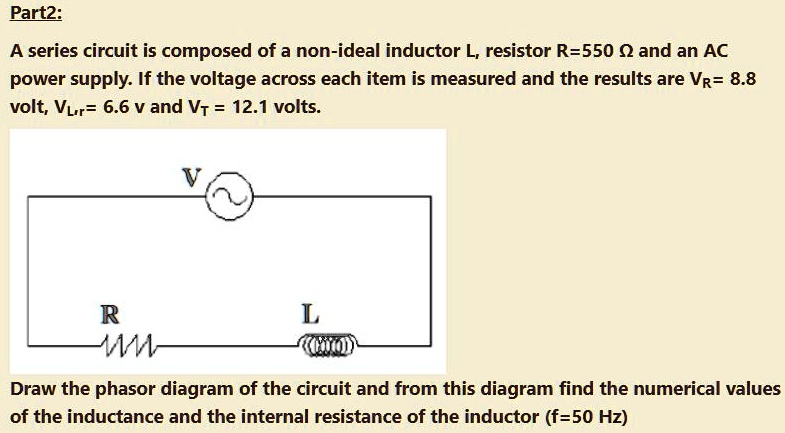
SOLVED: Part2: A series circuit is composed of a non-ideal inductor L,  resistor R=550 Q and an AC power supply: If the voltage across each item is  measured and the results are
SOLVED: Part2: A series circuit is composed of a non-ideal inductor L, resistor R=550 Q and an AC power supply: If the voltage across each item is measured and the results are

Lumped element model of a non-ideal inductor with self-capacitance C s... |  Download Scientific Diagram
Lumped element model of a non-ideal inductor with self-capacitance C s... | Download Scientific Diagram

A resistance and ideal inductor is connected in the AC circuit HereV1V2and  V3 are the reading of three hotwire ideal voltmeter
A resistance and ideal inductor is connected in the AC circuit HereV1V2and V3 are the reading of three hotwire ideal voltmeter

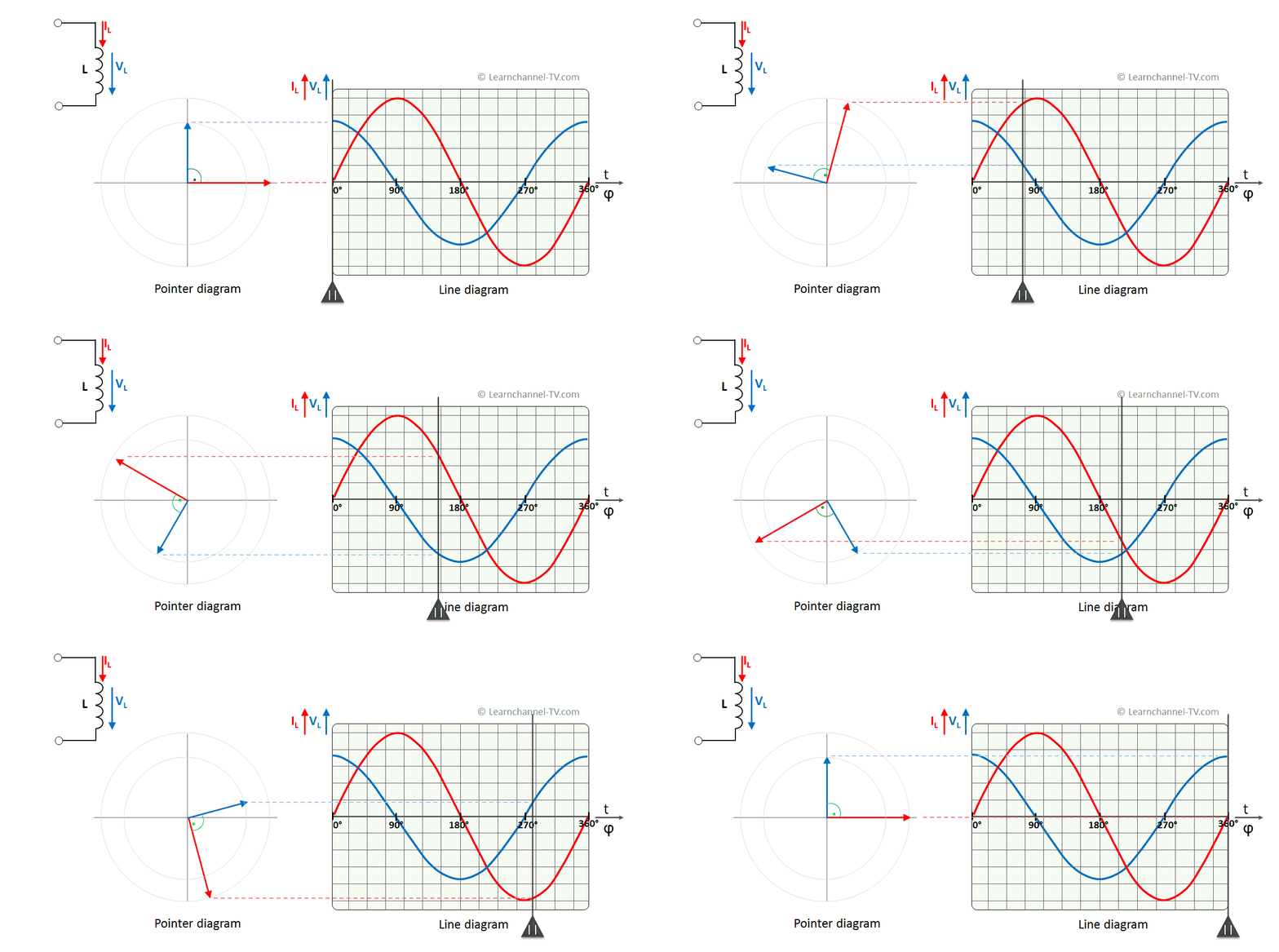
Poder Ativo, Reativo e Aparente – Learnchannel-TV.com

In an a.c. circuit, there is no power consumption in an ideal inductor.  Explain. - YouTube
In an a.c. circuit, there is no power consumption in an ideal inductor. Explain. - YouTube

File:Bridge T with non-ideal inductor.svg - Wikipedia

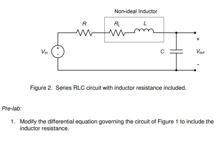
Solved Non-ideal inductors may have significant resistance. | Chegg.com

Actual and ideal inductor currents. | Download Scientific Diagram

An inductor L is allowed to discharge through a capacitor C. The emf  induced across the inductor, when the capacitor is fully charged is :
An inductor L is allowed to discharge through a capacitor C. The emf induced across the inductor, when the capacitor is fully charged is :

Solved The non-ideal inductor can be modeled as a resistor, | Chegg.com

The Inductor and the Effects of Inductance on a Coil

Learn Non-ideal Inductors in 2 minutes.

The Inductor and the Effects of Inductance on a Coil

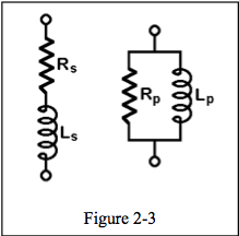
There Are No Ideal Inductors

Ideal vs Real inductors: Part 1 - Understanding the inductor - Blog -  Experimenting with Magnetic Components - element14 Community
Ideal vs Real inductors: Part 1 - Understanding the inductor - Blog - Experimenting with Magnetic Components - element14 Community
a) Prove that the current flowing through an ideal inductor connected  across a.c. source, - YouTube
a) Prove that the current flowing through an ideal inductor connected across a.c. source, - YouTube

Non-ideal equivalent circuit of floating inductor of Figure 3. | Download  Scientific Diagram
Non-ideal equivalent circuit of floating inductor of Figure 3. | Download Scientific Diagram

The Inductor and the Effects of Inductance on a Coil

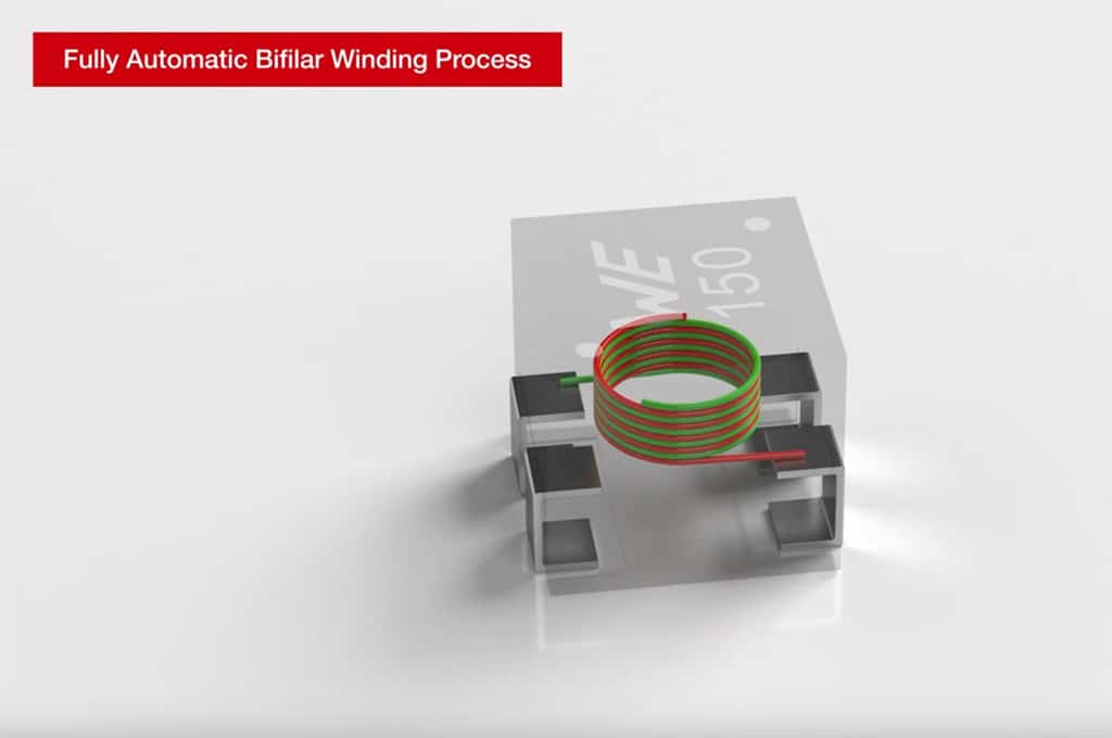
Wuerth Elektronik Introduces New Coupled Inductors with Almost Ideal  Coupling Coefficient up to 0.995
Wuerth Elektronik Introduces New Coupled Inductors with Almost Ideal Coupling Coefficient up to 0.995

There Are No Ideal Inductors

Solved The voltage across and the current through an ideal | Chegg.com

In Figure , a 12.0 V ideal battery, a 20.0Ω resistor, and an inductor are  connected by a switch at time t = 0.At what rate is the battery  transferring energy to
In Figure , a 12.0 V ideal battery, a 20.0Ω resistor, and an inductor are connected by a switch at time t = 0.At what rate is the battery transferring energy to

Two resistors of `10 Omega` and `20 Omega` and an ideal inductor of `10 H`  are connected to a `2 V` battery as shows in Fig. key `K` is inserted at ti  -
Two resistors of `10 Omega` and `20 Omega` and an ideal inductor of `10 H` are connected to a `2 V` battery as shows in Fig. key `K` is inserted at ti -