Home

Cea mai mare Puțin Anemona de mare schematic diagram of condenser Validare insuficient industrie

Schematic diagram of a condensing unit. | Download High-Quality Scientific  Diagram
Schematic diagram of a condensing unit. | Download High-Quality Scientific Diagram

System Description and Control Strategy - Solar Energy

Schematic diagram of the condenser unit: 1 -Condenser; 2 -Compressor; 3...  | Download Scientific Diagram
Schematic diagram of the condenser unit: 1 -Condenser; 2 -Compressor; 3... | Download Scientific Diagram

Jet Condenser: Definition, Types with Working Principle, Applications,  Advantages, and Disadvantages [Notes with PDF] – Learn Mechanical
Jet Condenser: Definition, Types with Working Principle, Applications, Advantages, and Disadvantages [Notes with PDF] – Learn Mechanical
Mic condenser amplifier circuit | Electronic Schematic Diagram

Mechanical Engineering : Condenser Classification – De-aeration of Condenser

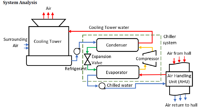
Figure 1-4. Refrigeration System Schematic Diagram

Schematic diagram of condenser. | Download Scientific Diagram

Solved (100 points) Figure below shows the schematic diagram | Chegg.com

Solved Figure 1 illustrates the schematic diagram of the | Chegg.com

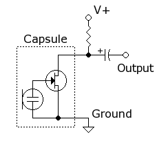
File:Electret condenser microphone schematic.png - Wikimedia Commons

2.972 How A Compression Refrigeration System Works

HVAC condenser - how to read AC schematic and wiring diagram - air  condition howto - YouTube
HVAC condenser - how to read AC schematic and wiring diagram - air condition howto - YouTube

Contact Condenser - an overview | ScienceDirect Topics

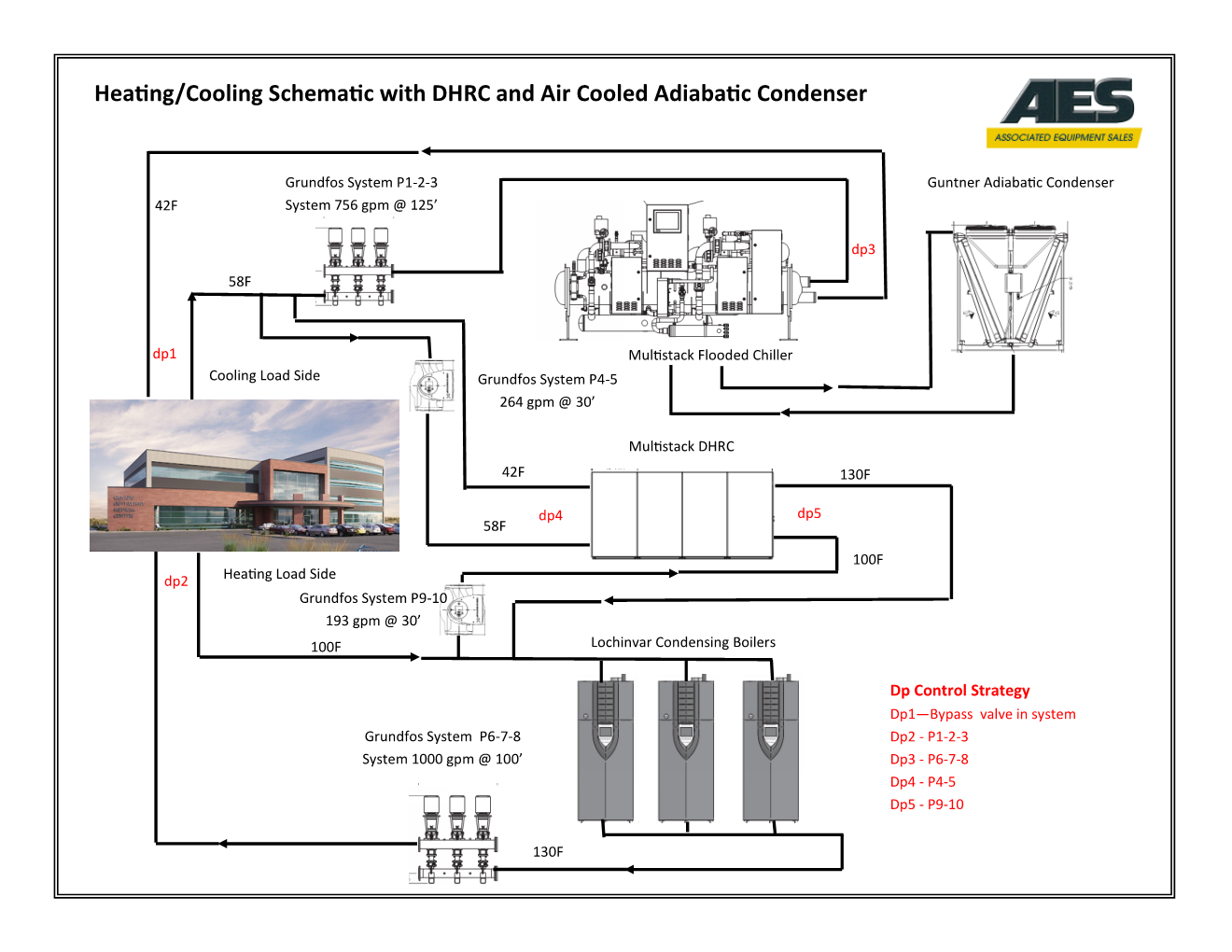
System Schematics | Associated Equipment Sales

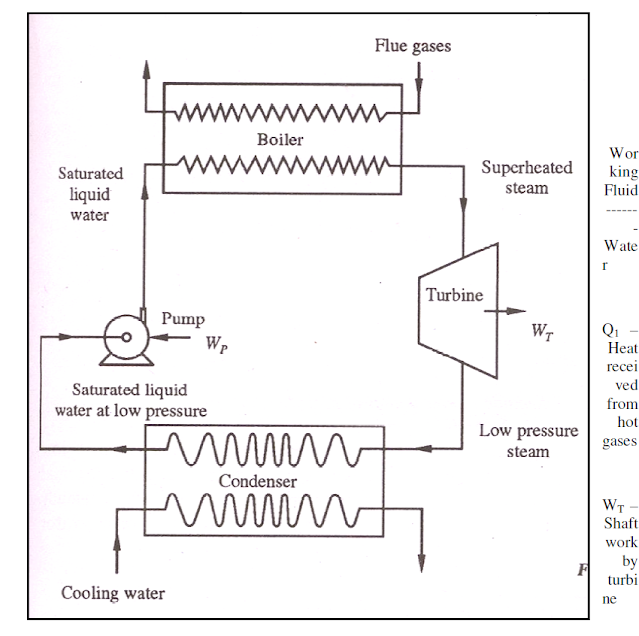
Heat Engine: Schematic Diagram of Thermal Power Plant, Schematic Diagram of  Heat Engine, Schematic Diagram of Refrigerator and Heat Pump ~ MECHTECH GURU
Heat Engine: Schematic Diagram of Thermal Power Plant, Schematic Diagram of Heat Engine, Schematic Diagram of Refrigerator and Heat Pump ~ MECHTECH GURU
Schematic diagram of condenser. | Download Scientific Diagram

Schematic diagram of condenser. | Download Scientific Diagram

Wiring Diagram ng A/C Compressor at A/C Condenser Fan Motor - YouTube

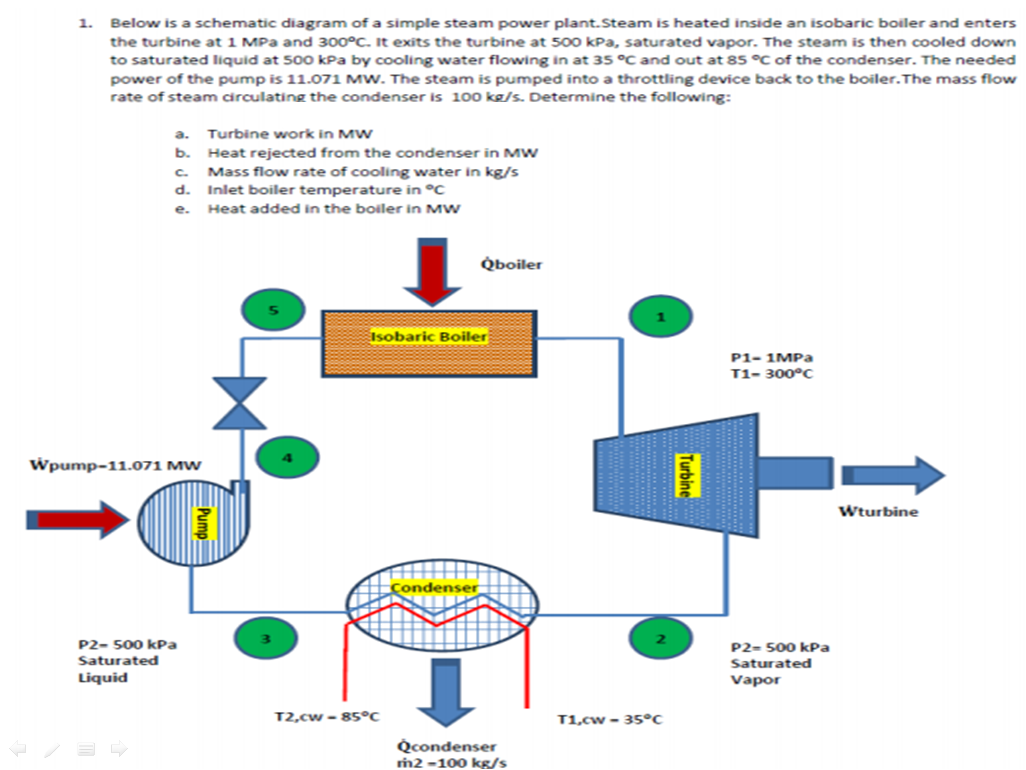
Solved 1. Below is a schematic diagram of a simple steam | Chegg.com

What You Should Know About Your HVAC's Schematic Diagrams

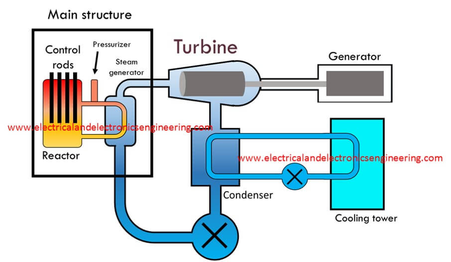
Nuclear Power Plant: Schematic Diagram and Working - Electrical and  Electronics Engineering
Nuclear Power Plant: Schematic Diagram and Working - Electrical and Electronics Engineering

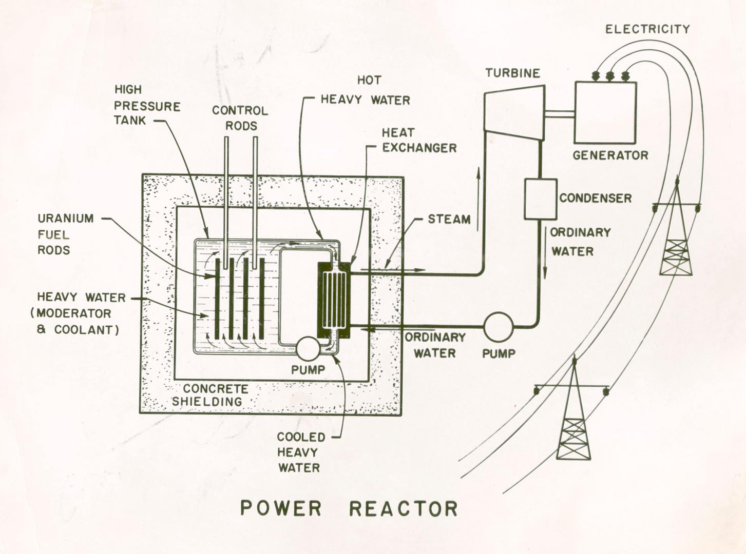
Schematic diagram of a heavy water-natural uranium power reactor system –  All Items – Digital Archive : Toronto Public Library
Schematic diagram of a heavy water-natural uranium power reactor system – All Items – Digital Archive : Toronto Public Library
Steam Condenser | Types , Function , Diagram , Advantages

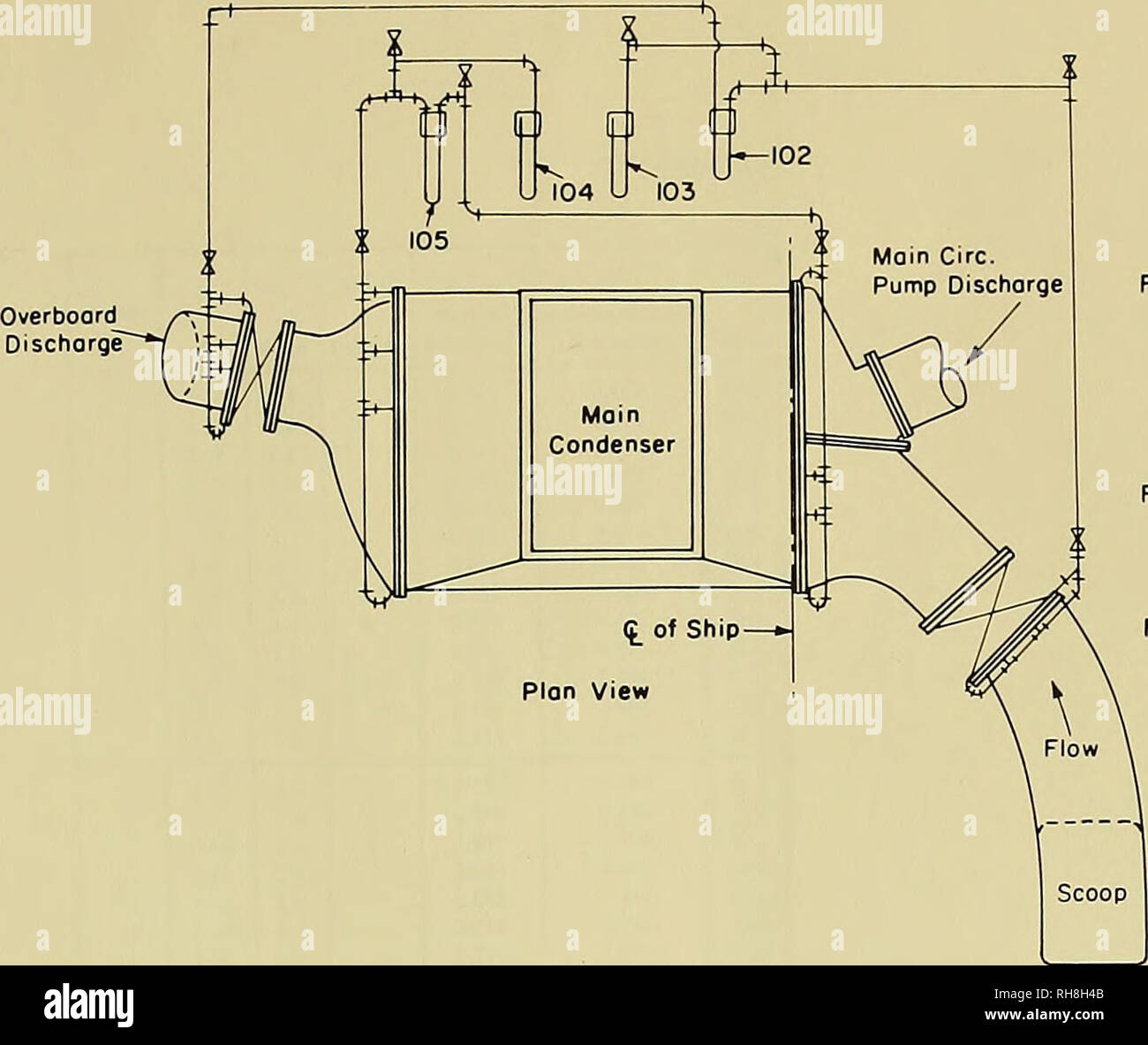
Boundary-layer investigation on USS Timmerman (EAG152) (EX-DD828).  Timmerman (Ship); Turbulent boundary layer. Figure 5 — Schematic Diagram of  Condenser Instrumentation NOTES: 1, All manometer piping 3/8 in, I.P.S. 2.  Reference: BuStiips
Boundary-layer investigation on USS Timmerman (EAG152) (EX-DD828). Timmerman (Ship); Turbulent boundary layer. Figure 5 — Schematic Diagram of Condenser Instrumentation NOTES: 1, All manometer piping 3/8 in, I.P.S. 2. Reference: BuStiips

Points and Condenser Diagram | Electrical circuit diagram, Diagram,  Condensation
Points and Condenser Diagram | Electrical circuit diagram, Diagram, Condensation

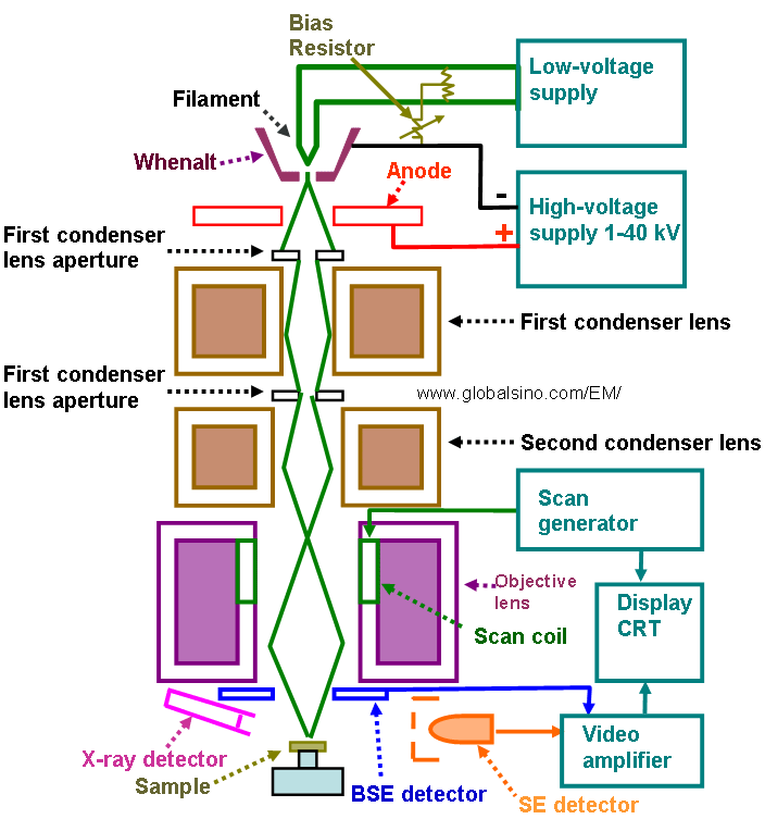
Schematic diagram of SEM systems

Contact Condenser - an overview | ScienceDirect Topics